Beetleweight Combat Robot
Custom engineered and fabricated combat robot constrained under 3lbs.
Time frame: November, 2019 - July, 2021
Introduction
Ever seen BattleBots the TV show before? If not, it’s essentially lots of 250-lb remote-operated robots that destructively battle in a contained box with high-power spinners, drums, or flippers. It’s hard to describe in text, so I would recommend looking up a quick clip online. The power stored in these weapons are unfathomable. These cost upwards of a luxury vehicle and more.
This project is similar to those robots but on a much smaller (and cheaper) scale. I decided to do this under the guidance and funding of the combat robotics club at WPI (sorta, more on that in a bit). A [project like this would allow me to delve into the world of combat robotics as well as gain familiarity and experience with the fancy machine shop tools available to me from my college. Sure, there are some vendors that sell functionally complete kits online, but where’s the fun in that?
The initial design was completed in November, 2019, and parts were purchased shortly after. Unfortunately, given the timeline of a busy spring semester and then a global pandemic, not much of this project has yet to come to fruition. Quite unfortunately, I also found out that the expected reimbursements from WPI only applied if the robot was completed then competed (at a local competition like Norwalk Havoc) within the same school year. Due to these circumstances, I was left with about $500 of electronic components and aluminum, steel, and plastic stock that I owned outright. Sad for my wallet, but it means I get to keep my robot!
Another busy school year mixed with pandemic restrictions, I wasn’t able to continue working on this project until the end of the 2021 spring semester.
Design
I designed the robot to be a drum spinner - in combat robotics, this entails where a “drum” with a few impactors (“teeth”) spins to inflict damage. Here is the design of the robot (late 2019):

The design goal for this robot aside from the “weapon class” was for it to be robust and powerful, with the drivetrain integrated within the main body of the chassis. The reason for this was that having watched countless BattleBots episodes and Beetleweight matches online, I noticed that wheels (and wheel guards) were usually among the first vulnerabilities of the robots. If the opponent disables the drivetrain, the match is essentially lost. With that in mind, my design houses the drivetrain all within the armor and chassis of the robot for extra protection, with a trade-off for robot width. It’s more than 7 inches wide! Another design goal I had in mind was to keep it simple - custom parts were to be easy to mill and if possible, accessible purchased components for electronics and other hardware.
The first CAD iterations of the robot actually had a solid aluminum chassis on all sides, but to my disappointment, I ran the weight analysis on Inventor and it was WAY too heavy. Instead, I opted for 3/8” thick ultra-high molecular weight polyethylene (UHMW) plastic bar stock for the side rails with an aluminum front panel. The side rails were constrained in the back with an appropriately-sized aluminum hex standoff and further covered with 3D printed TPU flexible plastic. The UHMW plastic side rails were a good solution for my weight problem as this material is strong and impact resistant. It was a new material for me as I had not worked with many other plastics, other than 3D printed polymers and Delrin (acetal) in the past. UHMW is a commonly used material in combat robotics. The top and bottom plates of the robot are also made with UHMW sheet stock as they need to protect the robot, and as for the bottom plate, be an integral part of the frame and mounting of other hardware. The chassis needed to be sized carefully to efficiently protect and hold all of the electronic components.
The drivetrain consisted of 3D printed PETG plastic mounts for two geared brushed DC motors with some commercial off-the-shelf (COTS) wheel hubs to accommodate the foam wheels. The weapon system was designed to have a de-coupled brushless motor within the frame so that it would not get damaged easily. Power from here was then transmitted to the drum via 3D printed pulleys and polyurethane round belting. The rest of the electronics were COTS solutions: 3S (12.6V) LiPo battery, a brushed dual motor controller for the drivetrain, a hobbyist electronic speed controller (ESC) for the weapon motor, a high-current switch, and lastly, a hobbyist receiver for remote control.
Now, onto the star of the show: the weapon! There are many ways to implement a drum spinner design and at first, I was lost. It could be machined billet material but my wide design would make it certainly difficult to manufacture, not to mention very heavy. Others include “eggbeaters” since they usually employ an lightweight frame for the weapon with heavy-duty impactors attached - resembling the kitchen tool. I found inspiration for my design looking at several unique designs that caught my eye. My drum spinner features several thin AR500 steel blades with an inner hexagonal profile that rotationally constrains them to a hexagonal shaft, which in turn, would spin upon a titanium dead shaft (“dead” meaning it is not spinning) using needle bearings. There are spacers in between these blades to keep them laterally constrained. You’ll also notice some pointy bits out front - these are Grade 5 titanium prongs that further protect the business end while also helping with getting under other opponents’ robots. While this weapon design isn’t perfect, it worked pretty well.
The final weight in CAD for the robot was a tad over 3lbs. I was a bit concerned as this didn’t account for the weight of the wires and various connectors; however, oftentimes things like 3D printed parts end up being lighter than expected. Additionally, the CAD analysis uses general material properties for the parts and isn’t always accurate. The final weight after assembly turned out to be 2lbs, 13oz!
Fabrication & Assembly
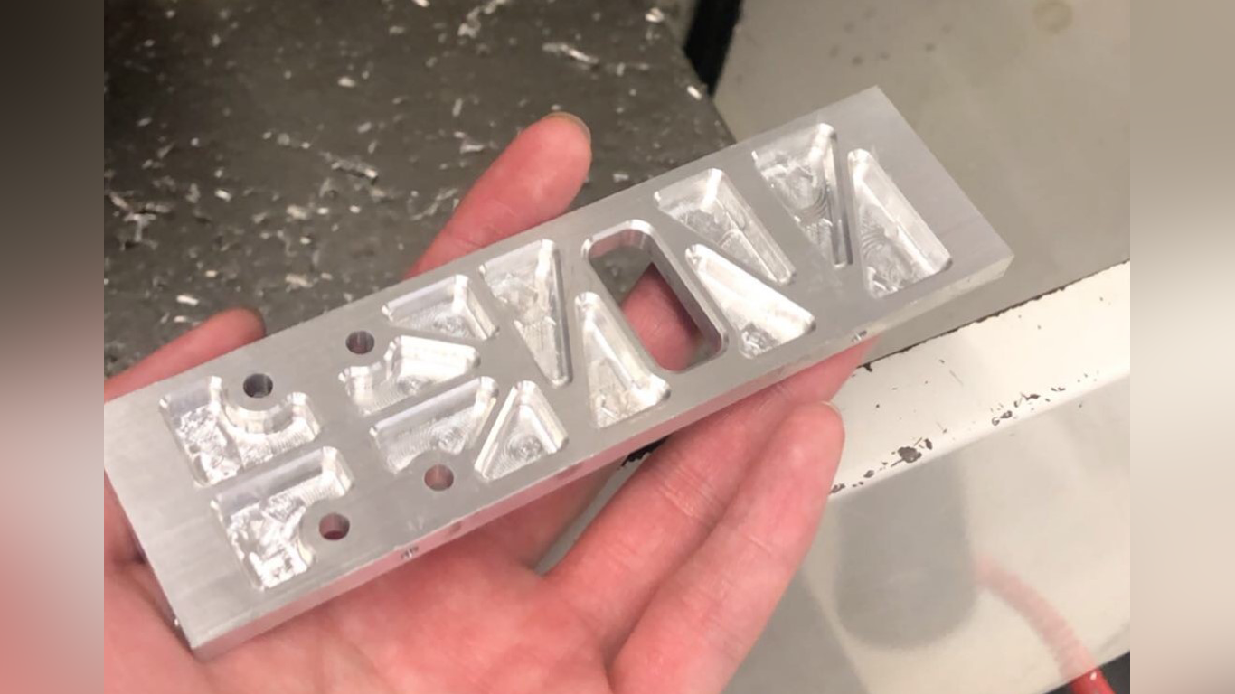
Milled Aluminum Front Panel
This was done on a Haas MiniMill at my school's machine shop and it took about 2 hours with several fixturing setups.
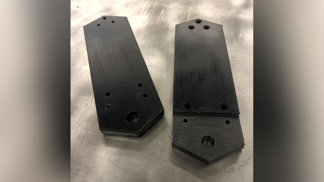
UHMW Side Rails
The UHMW side rails were also machined on the mill.
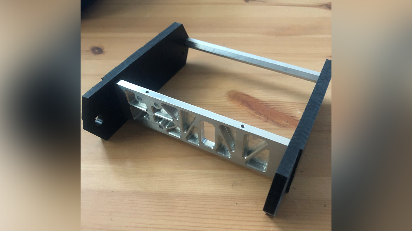
Chassis Mock-up
A mock-up of the basic chassis of the robot.
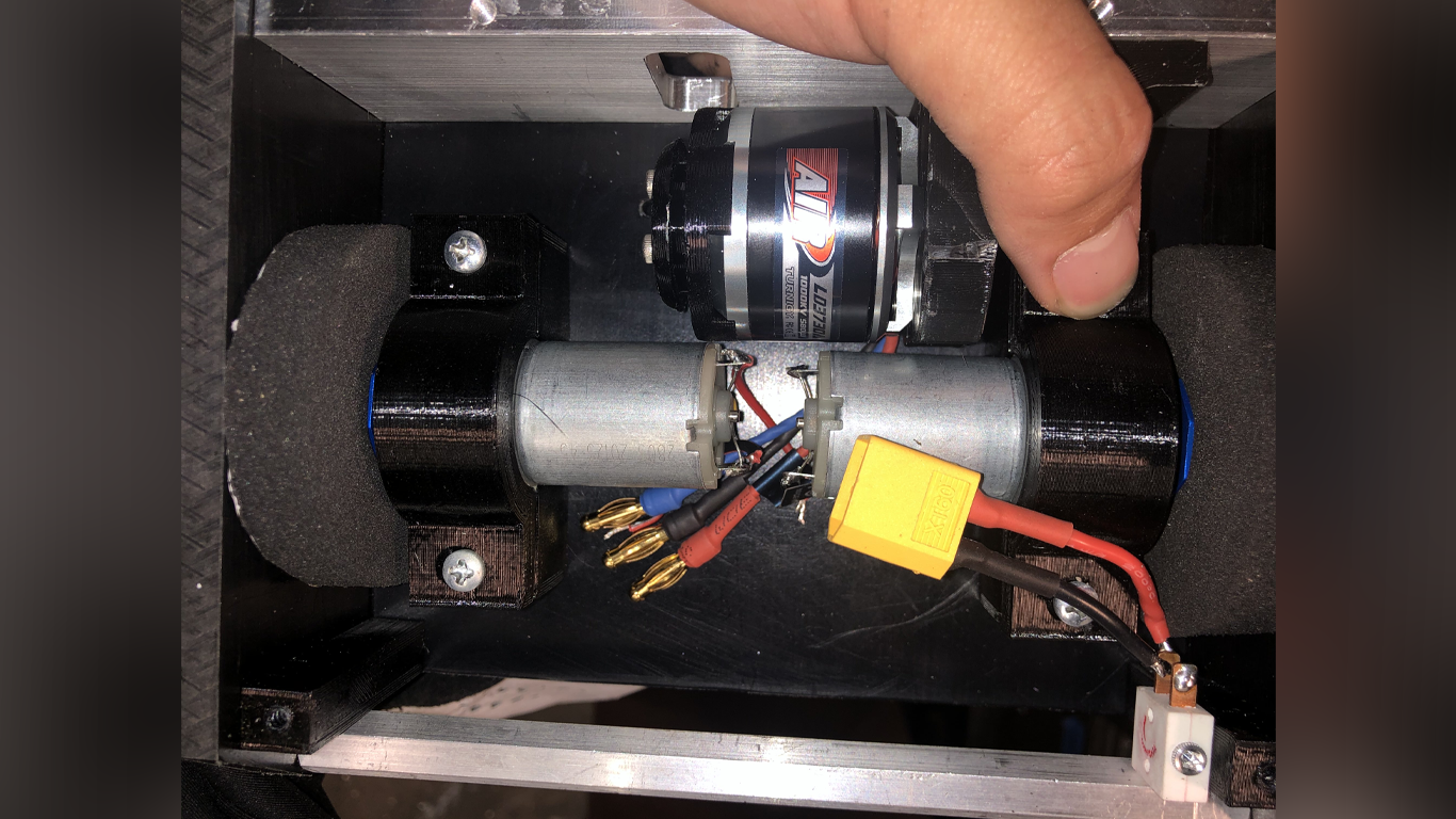
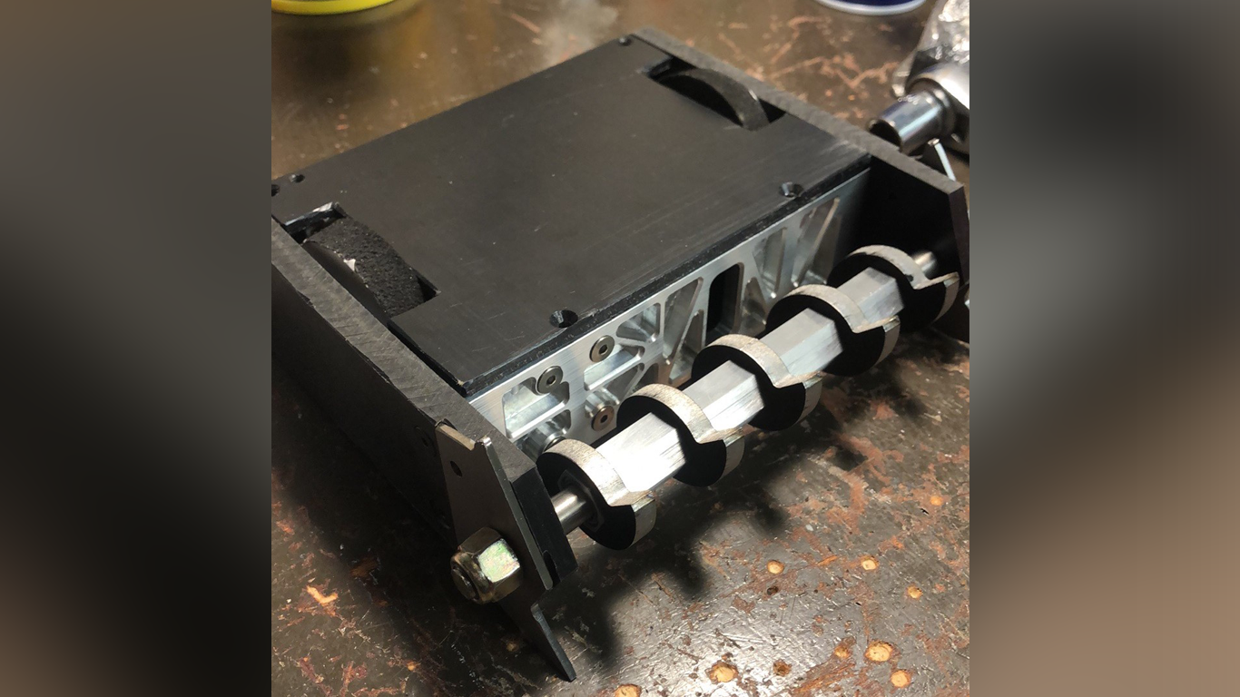
Electronics Bay
Some tight tolerances with the electronics bay! Not pictured is the battery and the rest of the control electronic components.
Almost Final Mock-up
We're getting there! Just needs some TPU spacers.
And I’m done! Photo was taken in a staging area at the July 2021 Norwalk Havoc competition.

Competition & Future Directions
In July 2021, I finally competed with my 3lb Beetleweight robot that was 1.5 years in the making! I was reasonably satisfied with the performance of my robot as it did what it was supposed to do! It drove well (but I definitely need more practice), and the weapon spun up. I won my first two matches but lost in the third elimination round to a very well-refined and powerful robot. It sustained some pretty good damage but the overall frame and chassis held out well. In this fight, I got hit on the side, and the opposing robot took a pretty nice chunk out of my UHMW side rail. I also had a weapon-to-weapon hit which sent me flying! This disabled my weapon and the impact shattered my PETG corner standoffs holding the top and bottom together, ultimately allowing the top plate to bulge out and leave me disabled and upside down. Upon further inspection after the match, I figured out why my weapon was disabled: the impact was hard enough to transmit through my steel teeth, through the aluminum hex shaft (which I thought would deform first), through the needle bearing (my next anticipated break-point), and finally onto my Grade 23 titanium axle, which bent ever so slightly but enough to restrict the bearings from rolling upon it. I couldn’t fix this before my match in the losers bracket, and had to forfeit (but this doesn’t count towards my overall 2-1 record! :) ). All in all, a pretty good first competition that I learned a lot from!
In my next iteration of my robot, I definitely need to make a new titanium axle. Grade 23 is a bit softer than Grade 5 but it was a cheap and available option on eBay when I was sourcing the parts. I am considering trying to harden it as well, to prevent any bending. You might be wondering why I’m not using a long, stiff, hardened steel shoulder bolt as the shaft as it doesn’t need to be machined and can be purchased easily - and to that, it is more than double the weight of my titanium axle and I cannot afford this increase in weight. To further mitigate my seized weapon should the shaft bend again, my friend suggested that this dead shaft could be implemented with a redundant pair of roller bearings housed in the side rails. It wouldn’t really be a dead shaft anymore, but should the needle bearings in the main weapon assembly seize, the motor would end up spinning the whole axle itself. The weight of two extra bearings is something I can afford.
I would also love to have a titanium wedge that spans across the front of the robot to better protect and deflect any weapons, especially horizontal spinners. I will need to find some more areas to reduce weight to accommodate for this wedge. As for some more minor changes, I’m switching out the PETG corner standoffs (colored blue at the back of the robot in the CAD model) with TPU. These will be more impact resistant and shouldn’t shatter with a big impact.
Total Cost: roughly $550, so far.