LED Light Tiles
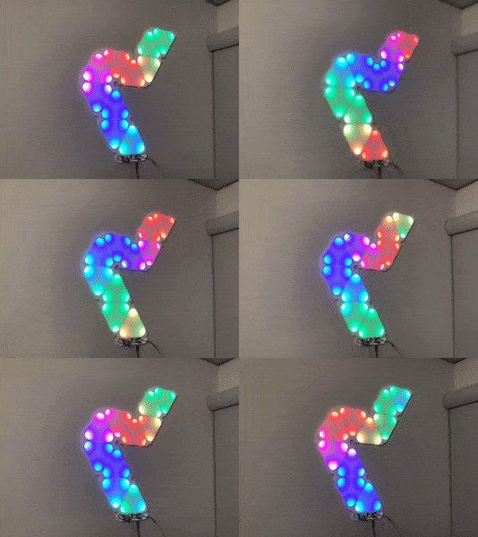
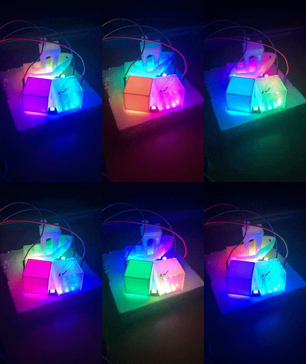
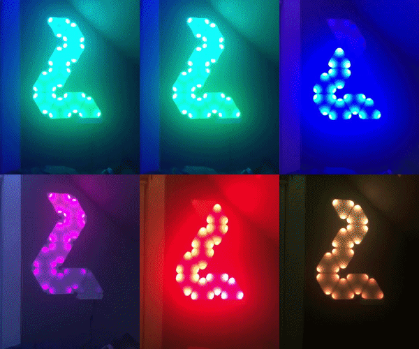
Custom 3D printed light tiles using programmable WS2812B LEDs, inspired by nanoleaf.
Time frame: January, 2019 - October, 2020

This project is inspired by the triangular RGB LED light tiles commercially available by the company nanoleaf. A passionate maker was inspired by the same product but was similarly not too stoked seeing the price. I decided to follow the open-source guide and design made available by this maker called moodlite.
These lights are highly customizable, Wi-Fi enabled wall tiles that have programmable LEDs and diffuse through white 3D printed parts, which brings a high-tech and colorful vibe to any room. There are limitless options in terms of integration, colors, and patterns.
I deviated from the main design in that I decided to place three LEDs per corner of the triangular tiles so that they would be brighter. I also initially opted to use a more powerful Arduino-based Wi-Fi chip: the ESP32 as opposed to the ESP8266.
While 3D printing appears to be a matter of clicking a few buttons and having the machine spit out parts, there is much more to that involving hundreds of hours of research that I may detail in a future post. The main difficulties in this 3D printing project involved bed adhesion for such a large surface area. While it seems counter-intuitive that a large surface area has trouble sticking to a print bed, the corners of these parts peeled up and caused warping of the print - in a project where flat and clean prints are imperative to the final product.
I also had to decide the color of my filament. There are many different brands and compositions, even in just PLA, so “white” isn’t a simple choice. The brand of white I had diffused well, and I also tested clear filament at different infill levels to see the effect.

The project involved a lot of careful planning and soldering between each strip of LEDs in each tile. Between each strip of LEDs and the edges of the tiles are 3-pin jumper wires (traditionally used for servo motors) that allow the tiles to be modular and rearranged in any pattern. One consideration I had while making this project was that the design used these Dupont wires and connectors to run a giant strip of LEDs in series. These are 28AWG wires that aren’t meant to take a lot of current, and with my reasonably conservative setup of 90 total LEDs, it would certainly be questionable. Each WS2812B LED can theoretically draw up to 60mA of current, which totals to over 5 Amps for my setup. I feared that these tiny wires would burn up under such loads, however seeing that many other people created this project with even larger setups, and that the 60mA rating for the LEDs were for white light at full brightness, I decided to roll the dice on this one and continue on.
The most challenging part was the programming on the microcontroller. I couldn’t manage to run even a basic test to drive the LEDs despite hours of research and combing through forums. I believe it had something to do with logic-level or timing, but even with a logic-level converter, it still didn’t work. The code base for this moodlite project is also open source. I wanted to just get the LEDs running so I currently run the tiles with a comparatively primitive Arduino Nano chip that is not Wi-Fi enabled, with some basic code. Earlier in 2020, I decided to give in and purchase an ESP8266 board which is what the project was designed to run on, but upon an initial test, I still had no luck even on vanilla moodlite code. I took a break on this project to work on some others.
Update 10/22/2020
Woohoo! I managed to get the software and tiles running yesterday afternoon. Whether I should’ve spent that time working on this project or my homework is a different subject. Not entirely sure what changed but it works as intended. I started by flashing the basic test code on the ESP32 board, and running a small test strip of the programmable LEDs powered by the 5V output from the board. It miraculously worked despite the fact that it didn’t in the past when I changed nothing. This also proved that a logic-level converter from the ESP32’s 3.3v data line to the LEDs’ 5V data was not necessarily needed to successfully drive the LEDs (but it would be good practice to do so in the future). I also flashed the same basic code to the ESP8266 board, and it also worked. So, both of the Arduino-based Wi-Fi boards were now confirmed to work with my LEDs.
I proceeded to wipe the EEPROM of the ESP8266 board and flash the latest release of the moodlite software, and changed a few configuration settings to match my setup. The web server was up in a few minutes and I was able to access it through my browser and play with the web-side settings. I connected the LEDs the same (correct) way I have been, and to my delight, the commands sent from the server almost instantly were reflected in the patterns the LEDs showed. I’m really not sure what was different about this attempt other than using the latest release of the code, which may have fixed things. What was weird though was that the previous versions were also shown to work amongst the community of other makers who recreated this project. There was a slight error in the JavaScript back-end of the web server that disabled the custom RGB color-picking functionality, but after a quick search on the moodlite forums, this was solved.
I am extremely happy that this project is now fully complete, and my LED wall tiles can be controlled from my computer or any phone.

In the future, I intend to perhaps port IFTT protocols (or utilize the integrated MQTT capability) so the tiles can be controlled via voice assistants like the Amazon Alexa. Another cool feature would be to integrate sound-reactivity with a microphone module so it can change with the beat of some music.
Total Cost: about $80, including filament costs.
Last Updated: 10/22/2020