Autonomous Roofing Robot (RBE 2001)
RBE 2001 - Unified Robotics I
Introduction
Course objectives: This course introduces the foundational theory and practice of robotics engineering from the fields of computer science, electrical engineering, and mechanical engineering. The focus of this course is the effective conversion of electrical power to mechanical power, and power transmission for purposes of locomotion, and of payload manipulation and delivery.
Project objectives: Design, build, and program a robot that would manipulate small square plates made of plastic with defined weights. The manipulations involved picking up these plates from a platform, lifting them, and placing/removing them on/from an elevated structure - resemblant to the angled roof of a house. The robot was built upon a Pololu Romi Chassis kit with the Pololu 32U4 control board. The operation of the robot was to be entirely autonomous with the help of a suite of sensors, including Hall-effect encoders, IR reflectance sensors, and ultrasonic distance sensors. The only forms of user interaction were the initial placement/setup of the robot and several stop-points in the sequence for user confirmation (for safety).
Design & Fabrication Process
The design of this robot was a long and intensive process that incorporated all of the concepts and lessons covered in this course all while meeting the project objectives. The materials that were available for use in this project were the Pololu kit as well as miscellaneous hardware, such as nuts, bolts, screws, and bearings. A suite of VEX hardware was also available but our team decided against using it. The design had to accommodate the given materials and electronics - parts needed to interface with the Romi chassis and our motors and servos. With these parameters in mind, it was decided that the best choice of fabrication for this robot would be 3D printing. The design reflects special considerations to further optimize the parts for 3D printed manufacturing since one of my team members and I were well-experienced in this field. The major sub-systems of the robot were organized as follows: the chassis, the lifting mechanism (four-bar linkage), and the gripper to manipulate the plates.
The slideshow presentation below captures the full design process of the robot.
Click here if the presentation does not display properly.
Programming
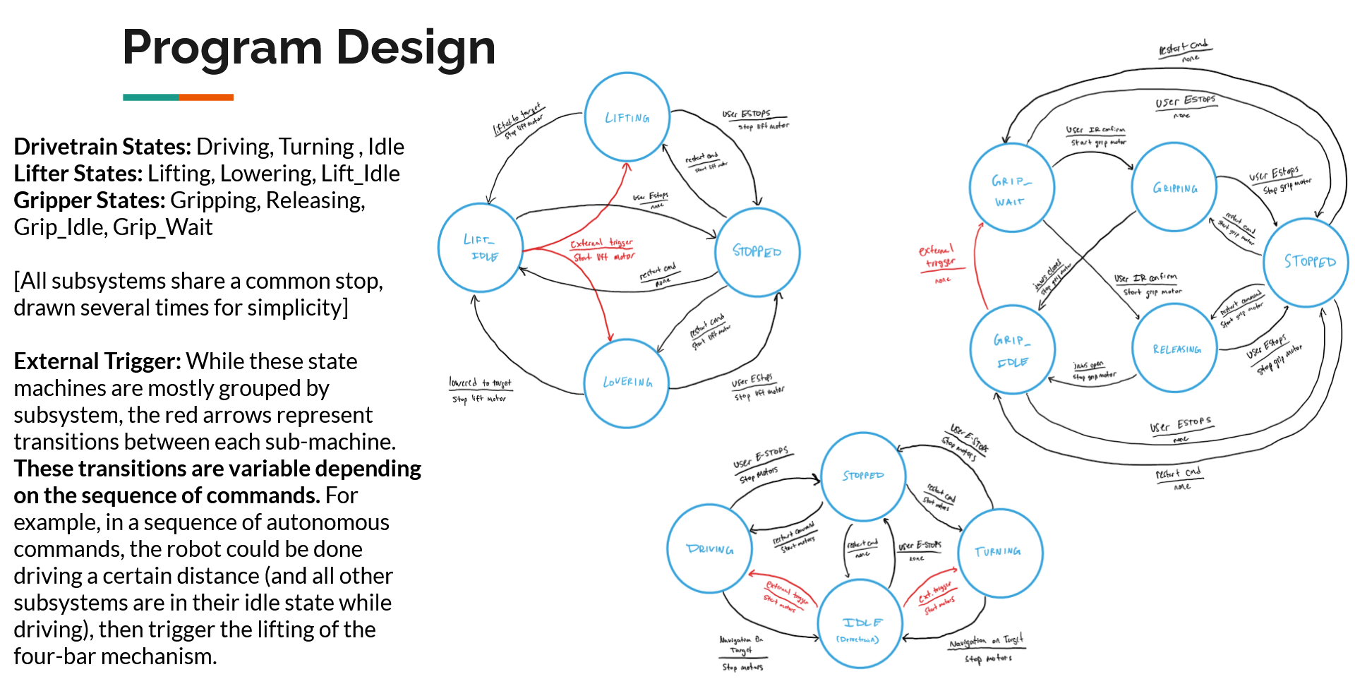
The control of this robot was based in C++ for the Pololu 32U4 control board which was Arduino compatible. The program design for the robot was centered around a state machine and the concepts of object-oriented programming. This non-blocking mechanism allowed for discrete control over the various “states” that the robot was in depending on the intended functionality/operation. It also allowed for “parallel processes” to occur within the program such as moving the robot while also reading from a sensor while checking for the user IR signal for an emergency stop. This is covered in slide 22 of the presentation but is shown again below.

One of the biggest challenges for the code was the non-blocking feature, since the state machine method was continuously looped in the program. As such, there could not be any arbitrary delays and every “piece” of the various actuator or sensor control functions needed to be optimized to work in such a structure. For example, the functions controlling the four-bar linkage motors needed to have setpoints that didn’t simply wait for it to finish within the implementation of the function, rather the completion would be checked externally in the respective state of the state machine such that it would be non-blocking.
The code below demonstrates a typical implementation of a state in the state machine utilizing non-blocking code to advance through its functions.
case DRIVE_REV_LIFT_1:
    // Line follow and drive in reverse until intersection, also raise arm to 25 deg roof height
    if(rangeFinder.getDistance() >= DIST_PLATFORM-0.3) {
        Serial.println("Chassis target reached.");
        chassis.drive(0);
    }
    blueMotor.startMoveTo(LIFTER_25ROOF * GEAR_RATIO_LIFTER);
    blueMotor.loopController();
    if (blueMotor.pullOnTarget()) {
        Serial.println("Lifter arm movement complete");
        blueMotor.setEffort(0);
        state = TURN_RIGHT_1;
        chassis.startTurn(84);
    }
break;
Aside from that, the next biggest challenge was the difference between embedded microcontroller programming for a robot and pure computer science. This distinction is one that I was familiar with but always have room to grow. A computer program will do what you ask - the only real source of error is the programmer. In contrast, programming a robot entails a variety of places that things can go wrong in, such as user error, sensor error, electrical problems, mechanical problems, environmental factors (i.e., friction), and so much more. This makes for an exponentially longer troubleshooting process and requires much more careful planning and design.
The code took several dozens of hours to develop and is complex. I cannot possibly detail on all the features and functionality here. In summary, some of the concepts that were implemented were:
- Non-blocking state machine
- PID control algorithms
- Median filters for increased sensor accuracy
See the full code on GitHub.
Conclusion
Overall, this project was a success. Our robot deliverable was packaged cleanly and neatly, with objectively the most robust design and construction. Much of the mechanical design was above-and-beyond using prior experience, such as keeping a low center-of-mass on the robot to increase stability and compressing the axles on the linkages for increased rigidity. In testing and final demonstrations, we were able to accomplish all of the established objectives along with some bonus objectives like manipulating a heavier aluminum plate.